Using USB-C connector for USB 2.0 Communication
Recently, I have been looking around to get a new keyboard. After spilling a certain sugar and cinnamon cereal on my keyboard, some of my keys are getting stuck in the down position. I tried may hardest to clean out the internal PCB, but I thought this might be a good time to do an upgrade.
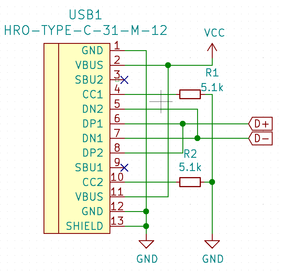
During my research phase, one of the key items that I want my new keyboard to have is USB-C. I needed a way to convert the USB 2.0 differential pairs into the signals used by the USB-C connector. After some meticulous research, I came upon a few schematic. After verifying that all the schematics are utilizing the same design and finding a reference in the USB-C handbook, I whipped up the following design.

Note that some modification will be needed depending on if your microprocessor has internal pull-ups for the data line or resistors on the data line.
References:
- Reclaimer Labs
Supporting Type-C from an existing USB2.0 design is straightforward and cheap (except for the connector). Basically you tie the DP pins together, tie the DM pins together, and add one pull-down resistor to each CC pin. This new Type-C device will identify as a data and power sink, use the default USB2.0 power of 500 mA, and work in either orientation of the plug.
- KiCAD Forums
Note that the user made a mistake in one of the schematics and used the USB A plug schematic and not the receptacle. Make sure to reference post 7.
